
Injection Moulding Design Guide
What is mould tooling and how is it made?
The mould tooling is the core of the injection moulding process, defining the shape, quality, finish and production efficiency of the parts. Tooling manufacture is the largest initial cost in manufacturing injection moulded parts and can determine the commercial viability of products. Tooling costs depend on many factors, but primarily:
- Size and complexity of parts
- Cost of tooling materials
- Machining required to manufacture the tooling
- Tooling features e.g: side actions, hot runners and cooling
By designing parts alongside the tooling, this ensures that an optimal end-solution can be reached which balances the part design, quality, lifecycle costs and production efficiency.
Components of a mould tool
In a simple two-part tool we typically have:
- Moving and fixed cavity plates – these contain the mould cavities which shape the parts
- Ejector system – for ejecting the parts from the cavity
- Risers – for providing space for the ejectors to move
- Clamp plates – for mounting the tool in the injection moulding machine
- Guide pins and sleeves – for aligning the cavity plates

For more complex parts tools may have more features. For example:
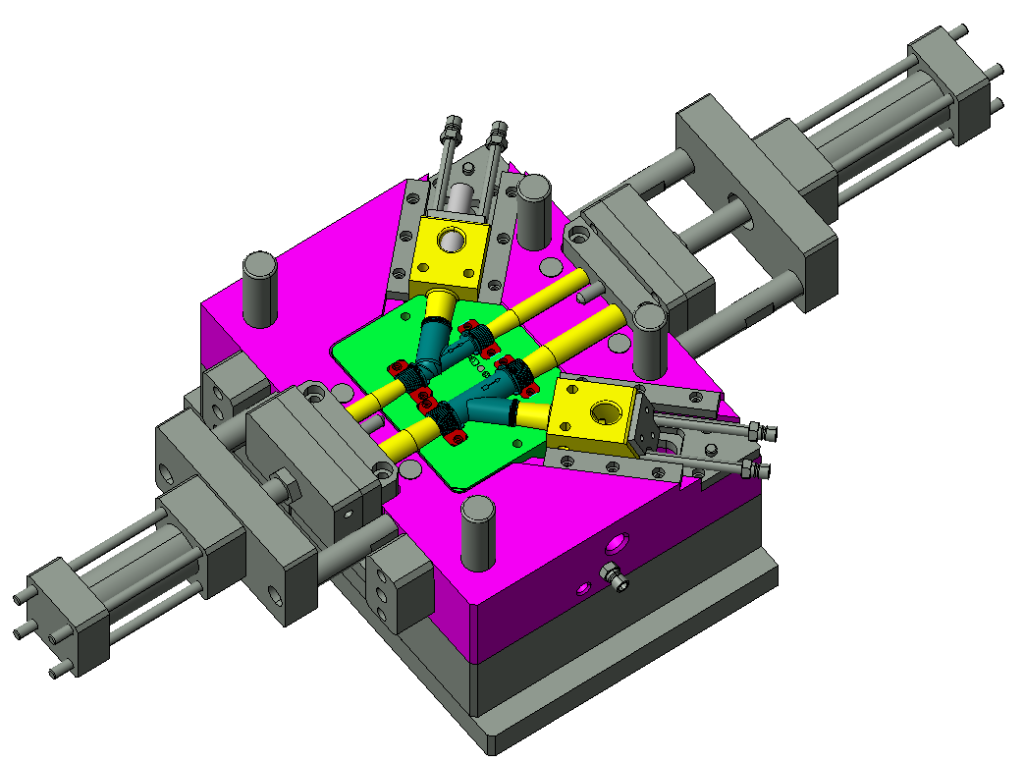
- Sliding, lifter and side core mechanisms – moving side action mechanisms enable undercuts and more complex part geometries.
- Inserts – removable components of the tool used for detailed and interchangeable features on parts.
- Hot runner systems – these keep the plastic molten into the mould cavity instead of using runners. Sometimes used in larger parts for reducing waste and controlling warpage.
- Heating systems – for precise control of mould temperatures.
Kit tools are often an option for low volume or low complexity parts. Kit tools often consist of aluminium cavity plates and an ejector system. They share parts with other tools to save tooling costs but require assembly before production.

Cavity Plates
The cavity plates are the main parts of the tool. These contain the mould cavities.
Moving half cavity plate:

The moving half opens to release the part. The part needs to ‘stick’ in this half so that the moulding machine can eject the parts with the ejector system. To help promote the part sticking to this side, the moving half usually contains the gates and runners, part features such as coring and ribs, and tooling features such as lifters, slides and other side actions.
Fixed half cavity plate:

The fixed half remains stationary (fixed) in the moulding machine. This half receives the molten plastic through the sprue bush. It contains more simple part geometry to promote part release.
Typically, this includes external features of the part such as external geometry and the visible surface finish of the part.
Part Layouts
The cavity plates are designed to make a tool which makes most economic sense for the parts.
The tool layout is a balance between expected production volumes, tooling cost, complexity of the parts.
Family and multi-cavity tools

Often it makes sense to fit multiple parts of a similar size in a single tool. The parts may be identical or different (for example part of a set). Multi-cavity tools have identical copies of a single part in one tool, and family tools have multiple different parts in one tool.
They offer reduced tooling costs as less work is required to manufacture the tooling. However tooling design can be more complex as cooling channels and any complex tooling features need to be designed to work together with other parts in the tool.
Family and multi cavity tools can also offer significant savings in production, as multiple parts can be made per shot and set up costs are reduced compared to running multiple tools. When cavities are not required, they can be blocked off to avoid waste material.
Single cavity tools

For larger or more complex parts, single cavity tools are often used. These allow for a more optimised tooling design such as side actions, cooling channels and other tooling features. The features in the tooling are not compromised by other parts, which may help in increasing part quality or shortening cycle times.
Manufacturing the tool
Tooling may be manufactured in-house or by external suppliers, using a variety of machining processes. Typically, the bolsters (blank tooling) are purchased from mould tool suppliers. The bulk of the work in manufacturing tooling is in machining the cavities and ejector system.
Most tooling is made with a combination of CNC manufacturing techniques, such as milling, turning and EDM.
CNC machining using milling or lathe operations are often used to machine cavities. Milling operations are the most economical method of machining as less machining operations are required, however with the trade off of less control over surface finish and less flexibility with geometry. If designing parts where the tool is to be milled, the machinability of the tool design must be considered, for example by using external radii and considering cutting depth in the cavities. As a guide cutters down to 1mm may be used but this depends on the tool material.

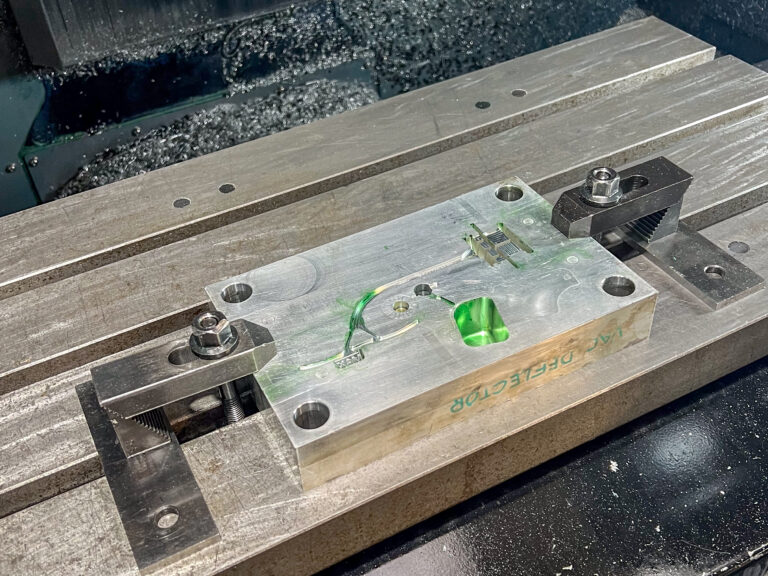
CNC or manual machining processes such as drilling are also used for parts of the tool such as the ejector system, cooling channels, runners and the sprue bush.
EDM Die Sinking (or spark erosion)


Electro Discharge Machining (EDM) Die Sinking can be used for more intricate features of a cavity, where surface finish is important, or for harder tool steels. It allows features to be made which cannot be achieved with a rotary cutter, for example features with no corner radii.
Copper electrodes are machined as a reverse of the feature in the tool – in other words they are positive for the finished part – or element of the finished part. They are then sunk into the cavity plates with an electrical current applied. The spark between the electrode and the steel erodes the cavity plates, resulting in high precision geometry in the tool which matches the geometry of the electrode. The surface finish can be varied depending on the machining parameters.
EDM Wiring


Electro discharge machining (EDM) wiring enables complex and high precision features to be machined through the depth of the cavity plates. This process uses a continuous roll of brass wire (typically 0.25mm diameter) with a current applied to cut the metal to high precision. Wiring is typically used to cut custom ejector shapes, ejector pin holes, and cavity plate inserts, where tight tolerances are required to avoid flash.
Wire erosion can be done in 2 axes, (the cut is vertical in the machine) or 4 axes (the top and bottom of the wire move relative to each other and to the workpiece) to cut tapered inserts, and other more complex features. Wire EDM is accurate to 0.01mm, so can be used to make tooling parts very accurately. Fully hardened materials can be cut.
Laser engraving is used to engrave features such as text, logos and custom surface finishes on to parts. It is also possible to use deep metal laser engraving to machine intricate cavities which would otherwise be difficult to machine with conventional machining techniques, and to create very precise decorative finishes.
FAQs
What are injection moulding tools made of?
Injection moulding tools are typically manufactured from steel or aluminium, depending on the requirements of the project.
Steel tooling is highly durable and offers excellent strength, making it ideal for high-volume production. However, it is more expensive to manufacture.
Aluminium tooling is faster and cheaper to machine, making it a good option for prototypes or shorter production runs. It is less durable than steel and not suited to abrasive materials.
At AAV Plastics, we frequently use the following grades of material for our tooling applications:
• Alimex ACP 7 aluminium
• P20 / DIN 1.2738 pre-hardened mould steel
• H13 / 1.2344 tool steel
Choosing the right tooling material is critical to achieving cost-efficiency, part quality, and tool longevity.
Want tailored advice on the best tooling material for your project? Get in touch with our team today.
What is the service life of an injection moulding tool?
How long does an injection moulding tool last?
The service life of an injection moulding tool depends on several factors, including the material of the tool, the type of plastic being moulded, and the complexity of the part design.
Aluminium tools generally have a shorter lifespan than steel, typically lasting between 50,000 and 100,000 shots. However, with the right application and care, we have seen aluminium tools remain in service for over 600,000 cycles.
Steel tools are far more durable, with an average service life ranging from 500,000 to 1,000,000 cycles, making them the preferred choice for long-term, high-volume production.
Selecting the right tooling material for your project can have a major impact on both cost and tool longevity.
If you’d like advice on maximising tool life for your specific application, contact our expert team today.
What is the cost of an injection moulding tool?
The cost of an injection moulding tool can vary significantly depending on the size, complexity, and requirements of your project. Prices can start from as little as £1,000 for simple, small-scale tools, while extremely large or complex tooling for high-volume production can exceed £1,000,000.
Several factors influence tooling cost, including:
- Part size and complexity – intricate designs or larger moulds require more advanced tooling.
- Tooling materials – aluminium tools are generally more cost-effective, while steel offers durability for long production runs.
- Machining and manufacturing – precision machining, EDM, and CNC work all impact the final cost.
- Special tooling features – elements such as side actions, hot runners, or complex cores increase complexity and expense.
At AAV Plastics, we offer expert guidance to balance performance, cost, and production volume, ensuring your tooling investment delivers long-term value.
Contact us today for a tailored quote or to discuss the best tooling solution for your project.
What are the advantages of an aluminium injection moulding tool?
Aluminium tooling is significantly more cost-effective to manufacture than steel, though it has a shorter service life. This makes it an excellent choice for market trials, technical validation, and low to medium production runs, where speed and cost-efficiency are key.
At AAV Plastics, we further reduce time and cost to market with our unique kit tooling system. In this approach, AAV retains ownership of the mould base, and customers only purchase the cavity plates and ejector system. This innovative solution lowers upfront investment while still ensuring high-quality, reliable tooling for your project.
What are the disadvantages of an aluminium injection moulding tool?
While aluminium tooling offers lower cost and faster turnaround, it does have limitations compared to steel. Aluminium tools have a shorter service life, making them less suitable for very high-volume production. In addition, they restrict material options, as abrasive plastics cannot be moulded without excessive wear.
Why make an injection moulding tool in the UK?
Manufacturing injection moulding tools in the UK offers significant advantages for businesses. By working with a UK-based toolmaker, you gain direct access to specialist expertise and technical support throughout your project. Lead times and shipping costs are reduced compared to overseas suppliers, while customer service is faster and more responsive.
In addition, UK tooling is less vulnerable to global supply chain disruptions, ensuring greater reliability and continuity. Choosing a local partner like AAV Plastics means better collaboration, higher quality assurance, and long-term support for your tooling investment.
Why make an injection moulding tool overseas?
Manufacturing an injection moulding tool overseas can provide a significant cost advantage, making it an attractive option for certain projects. Lower production costs often mean reduced upfront investment, which is particularly beneficial for large or complex tools.
At AAV Plastics, we work closely with trusted Far Eastern tooling partners who share our commitment to quality, reliability, and precision. This ensures our customers benefit from competitive pricing without compromising on standards. Every overseas tool is fully supported by our in-house team, who handle repairs, modifications, and maintenance to guarantee long-term performance.
However, overseas tooling can come with longer lead times and higher shipping costs compared to UK-based manufacture.
At AAV plastics we help our customers reach a cost-effective solution, exploring all options and choosing the best one for your project scenario.
What maintenance is required for an injection moulding tool?
Proper injection moulding tool maintenance is essential to extend service life, ensure consistent part quality, and prevent costly downtime. Key maintenance practices include:
- Regular cleaning of the tool face to remove residue and contaminants.
- Preventative protection, such as applying corrosion inhibitors (tool guards).
- Draining cooling channels to ensure all water is removed when the tool is not in use.
- Lubrication of moving parts, including ejector pins and slides.
- Servicing and refinishing of the tool face or other surfaces as required to maintain precision.
By following a proactive maintenance routine, tooling remains reliable, efficient, and ready for high-quality production.
At AAV our fully equipped toolroom allows us to make quick and efficient repairs as well as properly maintain your tools. We recognise that tooling a significant investment and do our upmost to protect your assets.
Looking for expert advice on mould tooling? Contact AAV Plastics today. Our team is always happy to provide guidance, design support and practical solutions to help you achieve the best results for your project.